

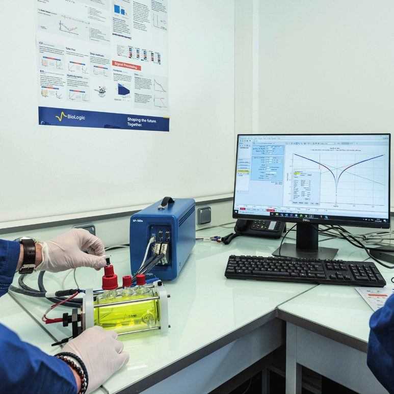
What is a potentiostat / galvanostat and how does it work?
1 Theory
The control loop
The potentiostat is a feedback control circuit that applies to the CE the voltage needed to hold the potential difference between WE and RE at the set value. The electrometer (a differential amplifier of very high input impedance) reads the RE potential without drawing current; the control amplifier compares the reading with the set point and adjusts the CE driver; the current is measured across a measuring resistor (I/E converter) in the WE path. In galvanostat mode the loop is inverted: the current set point is held and the potential is measured. Modern instruments offer both modes in a single hardware together with the AC superimposition needed for EIS.
Basic specifications and what they mean
The compliance voltage is the highest voltage that can be applied to the CE; if it is insufficient on high-resistance cells the instrument loses control. The current ranges and the resolution on the lowest range are decisive in picoampere-level sensor and corrosion measurements. Bandwidth and slew rate set the limit of fast-scan CV and high-frequency EIS. Electrometer input impedance (≥ 10¹² Ω) and input bias current determine the measurement error when working with high-impedance reference electrodes. 'Floating' (ground-isolated) operation is mandatory on grounded samples (autoclave, pipeline, grounded cell).
Stability
The potentiostat together with the cell forms a feedback system; the capacitance of the cell and the resistance of the reference electrode add phase lag to the loop. If the phase margin is exhausted the system oscillates and the data is corrupted. Manufacturers therefore offer bandwidth options, stability filters and the recommendation of a small capacitor/resistor in parallel with the reference electrode. Typical symptoms of stability problems are an irregular, oscillating current in CV and artificial inductive/capacitive tails at high frequency in EIS.
How is accuracy specified?
DC accuracy is given as a percentage of full scale + a percentage of reading; EIS accuracy is shown by contour plots in the impedance-magnitude–frequency plane. The honest way to compare two instruments is to read the error band in the same impedance and frequency region; a single 'maximum frequency' figure is misleading.
2 Application in measurement
A potentiostat is a feedback control circuit that holds the potential of the working electrode at the desired value relative to the reference electrode and supplies the current required for this through the counter electrode. In galvanostat mode the current is controlled and the potential is measured. Modern instruments (e.g. Bio-Logic SP-300, VMP-3e; Entek Potentio Galvano Scan) offer both modes in the same hardware.
Basic components: a high-input-impedance electrometer (≥ 10¹¹–10¹² Ω so that no current is drawn through the reference), the control amplifier, the current-to-voltage converter and the current ranges. A large number of current ranges (13 ranges in the Premium series, 1 pA – 1 A) allows both nA and A levels to be measured accurately.
Decisive parameters in selection: voltage compliance, maximum current and booster options, lowest current range/accuracy, bandwidth and rise time, EIS frequency range, number of channels, floating mode, software and expandability.
3 Applicability
Where it applies
- The hardware basis of every electrochemical experiment; prioritising the right specification (current range, bandwidth, floating, EIS accuracy) by application when selecting an instrument.
Limits and caveats
- In very high-current (hundreds of amperes) or very high-voltage (stack) systems a standard potentiostat alone is not enough; a booster, a load or a multichannel battery cycler is required.
4 What did the application notes find?
- Battery AN4 — Shows with examples that potentiostat stability is a feedback problem depending on the cell impedance and the reference-electrode resistance, and how the bandwidth setting and an RC network in parallel with the reference eliminate oscillation.
- Battery AN54 — Explains how to read the EIS accuracy contour plot; where the 0.3 %, 1 % and 3 % error bands lie in the impedance–frequency plane and that instrument comparison must be made on this basis.
5 Which instruments perform this measurement?
References
- book A. J. Bard, L. R. Faulkner, H. S. White. Electrochemical Methods: Fundamentals and Applications (3rd ed.). Wiley, 2022.
- article N. Elgrishi, K. J. Rountree, B. D. McCarthy, E. S. Rountree, T. T. Eisenhart, J. L. Dempsey. A Practical Beginner's Guide to Cyclic Voltammetry. J. Chem. Educ. 95, 197–206, 2018. doi:10.1021/acs.jchemed.7b00361 open access
- web Bio-Logic. Electrochemistry & Battery Testing Instrument Catalogue EC-BR-034-h. Bio-Logic, 2026. link