

Bio-LogicBio-Logic Science Instruments — Authorized Distributor for Türkiye
+90 (312) 437 40 77  ·  [email protected]
TR/EN
Get a Quote
Curriculum · Module 1 · Beginner

Potentiostat, Galvanostat and the Measurement Set-up

Data acquired without knowing how the instrument works and which errors the set-up produces is not reliable.

What is a potentiostat / galvanostat and how does it work?

Frequently searched:what is a potentiostatwhat is a galvanostathow does a potentiostat workchoosing a potentiostat

1 Theory

The control loop

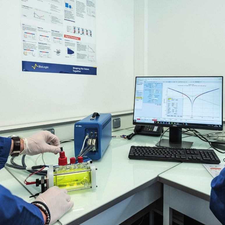
The potentiostat is a feedback control circuit that applies to the CE the voltage needed to hold the potential difference between WE and RE at the set value. The electrometer (a differential amplifier of very high input impedance) reads the RE potential without drawing current; the control amplifier compares the reading with the set point and adjusts the CE driver; the current is measured across a measuring resistor (I/E converter) in the WE path. In galvanostat mode the loop is inverted: the current set point is held and the potential is measured. Modern instruments offer both modes in a single hardware together with the AC superimposition needed for EIS.

Basic specifications and what they mean

The compliance voltage is the highest voltage that can be applied to the CE; if it is insufficient on high-resistance cells the instrument loses control. The current ranges and the resolution on the lowest range are decisive in picoampere-level sensor and corrosion measurements. Bandwidth and slew rate set the limit of fast-scan CV and high-frequency EIS. Electrometer input impedance (≥ 10¹² Ω) and input bias current determine the measurement error when working with high-impedance reference electrodes. 'Floating' (ground-isolated) operation is mandatory on grounded samples (autoclave, pipeline, grounded cell).

Stability

The potentiostat together with the cell forms a feedback system; the capacitance of the cell and the resistance of the reference electrode add phase lag to the loop. If the phase margin is exhausted the system oscillates and the data is corrupted. Manufacturers therefore offer bandwidth options, stability filters and the recommendation of a small capacitor/resistor in parallel with the reference electrode. Typical symptoms of stability problems are an irregular, oscillating current in CV and artificial inductive/capacitive tails at high frequency in EIS.

How is accuracy specified?

DC accuracy is given as a percentage of full scale + a percentage of reading; EIS accuracy is shown by contour plots in the impedance-magnitude–frequency plane. The honest way to compare two instruments is to read the error band in the same impedance and frequency region; a single 'maximum frequency' figure is misleading.

2 Application in measurement

A potentiostat is a feedback control circuit that holds the potential of the working electrode at the desired value relative to the reference electrode and supplies the current required for this through the counter electrode. In galvanostat mode the current is controlled and the potential is measured. Modern instruments (e.g. Bio-Logic SP-300, VMP-3e; Entek Potentio Galvano Scan) offer both modes in the same hardware.

Basic components: a high-input-impedance electrometer (≥ 10¹¹–10¹² Ω so that no current is drawn through the reference), the control amplifier, the current-to-voltage converter and the current ranges. A large number of current ranges (13 ranges in the Premium series, 1 pA – 1 A) allows both nA and A levels to be measured accurately.

Decisive parameters in selection: voltage compliance, maximum current and booster options, lowest current range/accuracy, bandwidth and rise time, EIS frequency range, number of channels, floating mode, software and expandability.

3 Applicability

Where it applies

  • The hardware basis of every electrochemical experiment; prioritising the right specification (current range, bandwidth, floating, EIS accuracy) by application when selecting an instrument.

Limits and caveats

  • In very high-current (hundreds of amperes) or very high-voltage (stack) systems a standard potentiostat alone is not enough; a booster, a load or a multichannel battery cycler is required.

4 What did the application notes find?

  • Battery AN4 — Shows with examples that potentiostat stability is a feedback problem depending on the cell impedance and the reference-electrode resistance, and how the bandwidth setting and an RC network in parallel with the reference eliminate oscillation.
  • Battery AN54 — Explains how to read the EIS accuracy contour plot; where the 0.3 %, 1 % and 3 % error bands lie in the impedance–frequency plane and that instrument comparison must be made on this basis.

5 Which instruments perform this measurement?

References

  1. book A. J. Bard, L. R. Faulkner, H. S. White. Electrochemical Methods: Fundamentals and Applications (3rd ed.). Wiley, 2022.
  2. article N. Elgrishi, K. J. Rountree, B. D. McCarthy, E. S. Rountree, T. T. Eisenhart, J. L. Dempsey. A Practical Beginner's Guide to Cyclic Voltammetry. J. Chem. Educ. 95, 197–206, 2018. doi:10.1021/acs.jchemed.7b00361 open access
  3. web Bio-Logic. Electrochemistry & Battery Testing Instrument Catalogue EC-BR-034-h. Bio-Logic, 2026. link

What is ohmic drop (IR drop), how is it measured and corrected?

Frequently searched:IR dropohmic drop correctioniR compensationsolution resistance

1 Theory

Definition

Between the voltage V(t) applied by the potentiostat and the interfacial potential E(t) actually seen by the working electrode there is a difference caused by the resistance through which the current passes in the electrolyte and the connections: V(t) = E(t) + R_u·I(t). R_u is the 'uncompensated resistance' and comprises the electrolyte resistance between the tip of the reference electrode and the WE surface, surface films and cables. High current, a poorly conducting electrolyte (organic solvent, solid electrolyte) and a distant reference position magnify the effect.

Effect on measurements

In CV the peaks shift in the scan direction, the peak separation increases and the curve 'flattens'; this can be confused with slow kinetics. In the Tafel region the slope grows artificially and i_corr is underestimated. In battery charge/discharge the ohmic loss appears as a sudden voltage jump and directly affects power/efficiency calculations. In EIS, R_u is the high-frequency intercept of the Nyquist plot with the real axis — EIS is the most direct way of measuring R_u.

Measurement methods

(1) EIS: the high-frequency intercept; (2) current interrupt: when the current is suddenly interrupted, the first instantaneous drop of the voltage is R_u·I; (3) positive feedback: a loop inside the instrument that compensates a chosen percentage of R_u; (4) automatic techniques such as ZIR: measure the impedance at a single frequency at the start of the experiment and transfer the result to the compensation.

Correction and its limits

Correction can be made after the measurement (E = V − R_u·I) or during it (positive feedback). In positive feedback 100 % compensation leads to instability; in practice 80–90 % is the upper limit. The best strategy is to reduce the ohmic drop: bring the Luggin capillary closer, increase the supporting electrolyte, use microelectrodes and short, thick connections.

2 Application in measurement

The electrolyte between the reference electrode and the working electrode has a resistance (Ru); when current flows, a voltage of I·Ru drops across this resistance and the electrode sees a potential that differs from the one actually applied. The result: shifting/broadening of CV peaks, distortion of Tafel slopes, a high-frequency offset in EIS.

Ru is measured by current interrupt, the high-frequency intercept of EIS (ZIR) or positive feedback. On Bio-Logic instruments EC-Lab® automatically compensates a chosen percentage of the measured resistance; since over-compensation leads to oscillation, 80–90 % is a practical upper limit.

Bringing the reference close to the surface with a Luggin capillary, a highly conductive supporting electrolyte and a suitable cell geometry reduce IR drop at its source.

Key equations

  • E_true = E_applied − I·Ru

3 Applicability

Where it applies

  • Battery and supercapacitor cells with organic electrolytes, poorly conducting media, high-current electrocatalysis and corrosion Tafel analysis.

Limits and caveats

  • In very low-current (nA) sensor and microelectrode experiments ohmic drop can usually be neglected; unnecessary compensation adds noise.

4 What did the application notes find?

  • Corrosion AN27 — Shows how peak potentials and peak separation shift in CVs taken on the same system with different R_u values, and that the curves overlap after correction.
  • Battery AN28 — Compares R_u measured by EIS and current interrupt; shows that the value comes out low if the measurement speed is insufficient in current interrupt, and that EIS is more reproducible.
  • Battery AN29 — Shows that the ZIR technique determines R_u with a single-frequency EIS measurement at the start of the experiment and transfers it automatically to the following techniques; explains the choice of suitable frequency and compensation percentage.
  • Corrosion AN48 — Shows with a numerical example that ohmic drop is a source of systematic error in corrosion-current determination, that the error grows in proportion to R_u·i_corr and that correction is mandatory.

References

  1. article D. Britz. iR elimination in electrochemical cells. J. Electroanal. Chem. 88, 309–352, 1978. doi:10.1016/S0022-0728(78)80122-3
  2. book A. J. Bard, L. R. Faulkner, H. S. White. Electrochemical Methods: Fundamentals and Applications (3rd ed.). Wiley, 2022.
  3. article A. Ch. Lazanas, M. I. Prodromidis. Electrochemical Impedance Spectroscopy — A Tutorial. ACS Meas. Sci. Au 3, 162–193, 2023. doi:10.1021/acsmeasuresciau.2c00070 open access

Set-up errors: cabling, Faraday cage, floating mode and stability

Frequently searched:Faraday cage electrochemistryfloating potentiostatpotentiostat oscillationlow-current measurement noise

1 Theory

Noise sources

Noise in electrochemical measurements comes from three sources: mains-borne electromagnetic interference (50 Hz and its harmonics), the instrument's own electronic noise (thermal, 1/f) and physical processes in the cell (gas bubbles, stirring, temperature fluctuation). In low-current measurements (nA–pA) EM interference dominates; a Faraday cage, short shielded cables, preventing cable movement and avoiding ground loops are the basic measures.

Grounding and floating

In most instruments the WE of the potentiostat is close to virtual ground. If the sample is already grounded (pipe, tank, autoclave body, another grounded instrument) a current loop forms between the two ground points and the measurement becomes meaningless. Floating (isolated) mode is essential in this case. On multichannel instruments operating simultaneously, channel-to-channel isolation, and in cells sharing a common electrolyte, crosstalk must also be considered.

Reference-electrode impedance and EIS artefacts

A high-impedance reference electrode (clogged frit, dry capillary, ionic liquid) forms an RC filter with the instrument's input capacitance; phase lag and artificial semicircles appear at high frequency. On low-impedance cells, cable inductance causes the Nyquist plot to dip below the real axis. Remedies: a platinum wire + capacitor in parallel with the reference ('dual reference'), four-terminal (Kelvin) connection, twisted/short cables.

Good-practice checklist

Letting the cell equilibrate before measurement (stable OCP), validating the first measurement with a dummy cell, qualifying the noise level against standards such as ASTM G199, recording the temperature in every experiment and calibrating the reference electrode regularly are the prerequisites of reproducibility.

2 Application in measurement

In pA–nA measurements ambient noise (50 Hz mains, instruments, movement) swamps the signal; a Faraday cage, short shielded cables, grounding discipline and a stable reference electrode are prerequisites. In high-frequency EIS, cable inductance and stray capacitances create spurious arcs.

Grounded cells (autoclaves, pipelines, some stacks) require floating mode, in which the instrument operates isolated from chassis ground; on Premium Bio-Logic instruments WE-to-GND and CE-to-GND connections make permeation and multi-electrode set-ups possible.

The stability of the control loop depends on the cell capacitance and cable length; the bandwidth (stability) setting is lowered on high-capacitance cells to prevent oscillation.

3 Applicability

Where it applies

  • Low-current measurements (corrosion, sensors, microelectrodes), electrochemical noise analysis, grounded industrial samples, high-frequency EIS.

Limits and caveats

  • In high-current battery cycling the instrument noise is usually far below the signal; here cable resistance and four-terminal connection are more decisive.

4 What did the application notes find?

  • Electrochemistry AN5 — Classifies the common error sources in EIS — reference impedance, cable capacitance, CE area, absence of a Faraday cage — and gives the practical measure for each.
  • Battery AN4 — Shows that an unstable potentiostat–cell loop can look like noise, and that the 'noise' disappears with the bandwidth and reference-RC correction.
  • Battery AN44 — Builds the full equivalent circuit including reference-electrode impedance and instrument parasitics; shows by simulation which artefact each element produces at which frequency.
  • Corrosion AN39-1 — Explains the qualification of the instrument's intrinsic noise against ASTM requirements; how to verify that potential and current noise are below the standard limits.

5 Which instruments perform this measurement?

References

  1. article A. Ch. Lazanas, M. I. Prodromidis. Electrochemical Impedance Spectroscopy — A Tutorial. ACS Meas. Sci. Au 3, 162–193, 2023. doi:10.1021/acsmeasuresciau.2c00070 open access
  2. book M. E. Orazem, B. Tribollet. Electrochemical Impedance Spectroscopy (2nd ed.). Wiley, 2017.
  3. web Bio-Logic Science Instruments. Learning Center — articles, application notes and tutorial videos. biologic.net, 2026. link

Technical Consulting and Quotation

Tell us your research goal and measurement requirements; our technical team prepares the suitable instrument configuration, accessories and a written quotation.

Quotation and technical consulting