What precautions should be taken for a good EIS measurement?
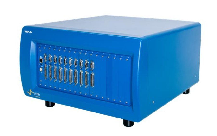
Cable length and layout, Faraday cage, reference-electrode quality, connection type (2/3/4-terminal), amplitude and frequency selection: the basic hardware and method checklist for a reliable impedance measurement; examples with the VMP3 (today VMP-3e) and VMP-300.
Sections of the note: Introduction · SOURCES OF ERROR · HIGH IMPEDANCE CELLS · LOW IMPEDANCE SAMPLES · Conclusion
Current model: The VMP3 has been discontinued; its current counterpart is the 16-channel VMP-3e.
Battery – Application Note 8
How is impedance data displayed: Nyquist, Bode, Black and admittance plots?
Different representations of the same EIS data highlight different information. The note compares Nyquist (−Im Z vs Re Z), Bode (|Z| and phase vs frequency), Black and admittance/capacitance plots with examples and shows how to obtain each in EC-Lab®.
Sections of the note: Impedance or Admittance Nyquist Diagrams · Impedance or Admittance Bode Diagrams · Impedance or Black Diagrams
Battery – Application Note 9
Is my system linear? How does the excitation amplitude distort the EIS result?
EIS relies on the small-signal linearity assumption. The note shows how harmonics appear as the amplitude grows, how the Nyquist plot is distorted and practical rules for choosing the right amplitude (Lissajous and THD checks).
Sections of the note: Introduction · Test Box-3 · Test Circuit #1 · Test Circuit #2 · Test Circuit #3 · Conclusion
Battery – Application Note 14
What is an equivalent circuit, and how is it built and fitted with Z Fit?
Basic use of Z Fit: building circuits from R, C, L, Q (CPE), W elements, initial values, minimisation algorithms and interpretation of results. The Randles circuit and common variants are illustrated.
Sections of the note: Introduction · Fitting an Experimental Nyquist Impedance Diagram Using ZFit · Equivalent Electrical Circuit · Transformation Formulae · Conclusion
Battery – Application Note 15
How do Kramers-Kronig transforms test the consistency of my EIS data?
Kramers-Kronig relations test the causality/linearity/stationarity condition between real and imaginary parts. The note explains, through two questions, what the EC-Lab® K-K tool does and does not say and how it exposes corrupted data.
Sections of the note: Introduction · What Can We Do with Truncated Impedance? · What Can We Do with an Unstable System Under Galvanostatic Control (GC)? · Test Box-3 Circuit 3 · Ni Electrode in Acidic Medium · Conclusion
Battery – Application Note 17
How is EIS corrected when the system drifts during the measurement?
For non-stationary systems, EC-Lab®'s patented drift-correction algorithm shows how data corrupted at low frequencies is corrected; when to use it and its limits are discussed.
Sections of the note: Introduction · Experimental Part · Impedance Measurement in Drift Conditions Toward A Steady State · Electrical Test Circuit · Principle of the Drift Correction Method Toward A Steady State · Study of A Lithium-Ion Battery
Battery – Application Note 18
How are potential-dependent EIS (SPEIS) and automatic sequential Z Fit performed?
Staircase PEIS takes EIS at each potential step; the results are automatically fitted with the same circuit and the potential dependence of the parameters is plotted (e.g. Mott-Schottky, passive film).
Sections of the note: Introduction · Experimental Part · Determination Of The Diode Parameters Value · Speis Measurement< · Automatic Successive Fits · Determination Of The Circuit Parameter’s Value
Corrosion – Application Note 19
What is multisine EIS, and when is it advantageous over single-sine measurement?
The multisine method, in which several frequencies are applied simultaneously, shortens measurement time at low frequencies. The note gives comparative results against single-sine and the EC-Lab® settings.
Sections of the note: Introduction · Experimental · Results · Conclusion
Corrosion – Application Note 20
What is pseudocapacitance (CPE), and how is it converted to a true capacitance?
If the centre of the semicircle lies below the real axis, a constant phase element (CPE) is needed. The note explains the meaning of the Q and α parameters, effective-capacitance calculation with the Brug and Hsu-Mansfeld approaches and the EC-Lab® pseudocapacitance tool.
Sections of the note: Introduction · Experimental Part · Conclusion
Battery – Application Note 23
How are EC-Lab® parameters set for EIS on a Li-ion cell?
The influence of amplitude, number of measurements per frequency, wait time, drift correction and connection choice (2/4-terminal) on obtaining correct results for low-impedance batteries is shown experimentally.
Sections of the note: Introduction · Experimental Part · Connection · Cable Length · Experimental Parameters · Conclusion
Battery – Application Note 42
When is the modified inductance element La needed?
The La element, the inductive counterpart of the CPE, is introduced for inductive arcs with shifted centres that rise above the real axis at high frequency; modelling of cable and winding effects in batteries is illustrated.
Sections of the note: Introduction · High-frequency inductance in Li-Ion batteries · Low frequency inductive behavior of a freely corroding metal · Conclusion · Appendix
Battery – Application Note 43
How is the transmission-line model for porous electrodes fitted in Z Fit?
The impedance of porous and battery electrodes is described with transmission-line elements. The note shows step by step the parameters of the transmission-line elements in EC-Lab® and the fitting strategy.
Sections of the note: Introduction · OPEN-CIRCUITED TRANSMISSION LINES $Z_\text L =1$ · OPEN-CIRCUITED URC (UNIFORM DISTRIBUTED RC) · OPEN-CIRCUITED URQ · SHORT-CIRCUITED TRANSMISSION LINES $Z_\text L = 0$ · SHORT-CIRCUITED URC
Which artefacts do reference-electrode impedance and instrument parasitics create in EIS?
Stray capacitances, reference-electrode resistance and cable inductance produce spurious semicircles and inductive loops at high frequency. The note builds the equivalent model and lists practical measures to reduce artefacts (short cables, low-impedance reference, Faraday cage).
Sections of the note: EIS Basics · Introduction · An Analysis Dilemma · Instrumentation Parasitic · Measurement Method · Potentiostat stray Capacitances
Corrosion – Application Note 45
How are several impedance diagrams fitted simultaneously with Z Fit?
Batch fitting of diagram series obtained in SPEIS or time-dependent measurements; automatic plotting of parameters against potential/time and weighting options.
Sections of the note: Introduction · Fitting Multiple Impedance Diagrams · Experimental Results · Li-Ion Batteries Application: SOC and SOH · Photovoltaic Cells Application · Corrosion: Polarization Resistance Evolution As A Function Of Time
Battery – Application Note 49
Potentio-EIS or galvano-EIS? Which one should be chosen in which case?
The difference between PEIS and GEIS, the advantage of galvano mode for low-impedance batteries, amplitude selection and the 'automatic amplitude adjustment' feature in EC-Lab® are explained with examples.
Sections of the note: Introduction · EIS measurements around the OCV · Continuous discharge · Conclusion
Battery – Application Note 50-1
EIS mathematics 1: Complex numbers and impedance diagrams
Why complex numbers best represent impedance, the relationship between modulus/phase and real/imaginary parts, and hand derivation of the diagrams of simple circuits.
Sections of the note: Introduction · Complex Number · Definition · Notations · Complex Conjugate · Plots of Complex Function
Battery – Application Note 50-2
EIS mathematics 2: Transfer function via the Laplace transform
Moving from time-domain differential equations to the frequency domain; obtaining the impedance of R, C, L and their combinations with the Laplace transform.
Sections of the note: Introduction · Definitions · Table Of Laplace Transforms · Transfer Function of a Linear and Time Invariant (LTI) System · Definition · Response of a LTI System
How is the instrument's EIS accuracy contour plot read?
The accuracy contour plot shows, as a function of impedance magnitude and frequency, in which region the measurement stays within error bands such as 0.3 % – 3 %; this is the honest way to compare different instruments.
Sections of the note: Introduction · Contour Plot · EIS Accuracy Contour Plot · SP-300 EIS Accuracy Contour Plot · Example · How to Use an EIS Contour Plot
Corrosion – Application Note 55
Why is EIS misinterpreted on time-varying systems?
In non-stationary systems such as corrosion and batteries, low-frequency data is corrupted by time variation. The note covers diagnosing the violation of the stationarity assumption and the measurement strategy (fast measurement, drift correction).
Sections of the note: Introduction · Impedance Diagram for Time-Variant System · R1+R2(t)/C2 Circuit with Increasing R2 · R1+R2(t)/C2 Circuit with Decreasing R2 · Stationary System Check · Kramers-Kronig (KK) Transforms
Battery – Application Note 60
What is the distribution of relaxation times (DRT), and when is it used?
DRT separates overlapping time constants without assuming an equivalent circuit. The note introduces the method, the regularisation parameter and interpretation of battery impedance with the EC-Lab® DRT tool.
Sections of the note: Introduction · Theory · Finite Voigt Circuit · Infinite Voigt Circuit · Experimental Data · The Problem
Corrosion – Application Note 64
What do the EIS quality indicators THD, NSD and NSR tell us?
The three indicators quantify linearity, stationarity and noise: high THD → reduce the amplitude, high NSD → increase the wait time, high NSR → increase the amplitude. How to record the indicators in EC-Lab® is shown.
Sections of the note: Introduction · Theoretical Description · Total Harmonic Distortion (THD) · Non-Stationary Distortion (NSD) · Noise to Signal Ratio (NSR) · Results on Electrical Circuits
Corrosion – Application Note 65
Which parameters affect the THD value, and how does it compare with other linearity tests?
The effect of harmonic count, amplitude, frequency and system type on THD; comparison with Lissajous and Kramers-Kronig and the limits of the 5 % threshold rule.
Sections of the note: Introduction · Parameters Affecting The THD · Edc1: Linear Behaviour · Edc2: Non-Linear Behaviour 1 · Edc3: Non-Linear Behaviour 2 · Summary
How is a non-stationary EIS measurement detected and corrected? (Corrosion example)
In a corrosion cell, the NSD indicator and drift correction are used together to correct corrupted low-frequency data; EC-Lab® steps are given with screenshots.
Sections of the note: Introduction · Experimental conditions · Results · How to check and correct time-variance using EC-Lab® · Perform EIS with galvano control · Non-Stationary Distortion (NSD) indicator
Battery – Application Note 69-2
How is a non-stationary EIS measurement corrected? (Battery cell example)
Application of the same method on a Li-ion cell: evaluation with NSD of EIS taken during post-charge relaxation and modelling of the corrected diagram with Z Fit.
Sections of the note: Introduction · Experimental conditions · Results · How to check and correct time-variance using EC-Lab® · Non-Stationary Distortion (NSD) indicator · “4D impedance” using Z Inst analysis tool from EC-Lab®
WP EIS QI
White paper: Systems and EIS quality indicators
A holistic assessment of typical values of the quality indicators in different electrochemical system types (battery, corrosion, sensor) and how they guide the measurement protocol.
WP Battery EIS
White paper: Studying batteries with EIS
What EIS measures in batteries (SEI, charge transfer, diffusion), SOC/SOH tracking, the advantage of native EIS and the requirements for a correct measurement; a comprehensive guide to get started.