

PEIS, GEIS or GEIS-AA? Which control mode should be chosen and when?
Potential-controlled EIS makes it easy to define a small amplitude; low-impedance and time-variant systems, however, need current control. GEIS-AA (adaptive amplitude) combines the advantages of both.
Key points
- Without prior knowledge, a potential amplitude of 5 - 20 mV is considered small; this is why PEIS is generally used.
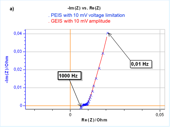
- Low-impedance systems (e.g. a Li-ion cell with a high-frequency impedance of a few mΩ): a small potential change produces a large current and the regulation loop struggles. Under current control a large current amplitude gives a small voltage response and the measurement is stable.
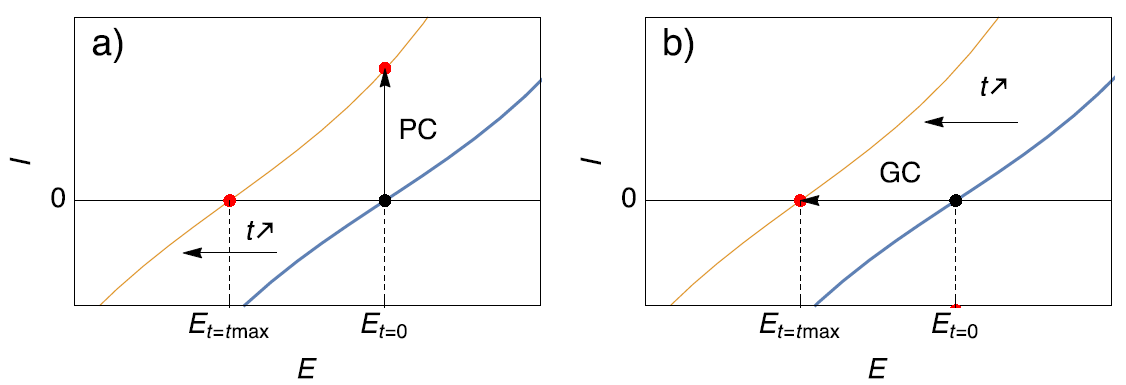
- Time-variant systems: as the corrosion potential drifts, PEIS stays at the initial potential and the measurement ends up at an anodic point. GEIS (I = 0) keeps the measurement at the actual corrosion potential at all times.
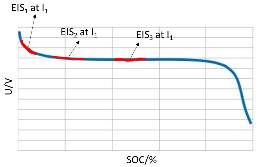
- In-situ EIS during charge or discharge can only be performed under galvanostatic control around a non-zero DC current.
- GEIS-AA: current is controlled while the amplitude is set in volts; the instrument adapts the current amplitude to meet the target voltage amplitude. The result is the same as a potential-controlled measurement, while keeping the current control required for time-variant systems.
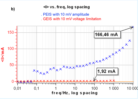
- In the battery example the mean DC current during PEIS reached 166 mA but stayed at about 2 mA with GEIS: controlling zero current stresses the cell far less than controlling the initial OCP.
Figures
Images: Bio-Logic Science Instruments; taken from the source article.
Related application notes
- Potentio-EIS or galvano-EIS? Which one should be chosen in which case? Battery AN49
- How are EC-Lab® parameters set for EIS on a Li-ion cell? Battery AN23
- White paper: Studying batteries with EIS WP Battery EIS
- Why is EIS misinterpreted on time-varying systems? Corrosion AN55
Related curriculum module: Electrochemical Impedance Spectroscopy (EIS)
Source: Bio-Logic Learning Center, “PEIS or GEIS or GEIS-AA? That is the question.” · Source updated: November 19, 2024
Copyright of the images and the original text belongs to Bio-Logic SAS.
Copyright of the images and the original text belongs to Bio-Logic SAS.