

Which equivalent circuit models the low-frequency inductive arc in acidic corrosion? (ZSim and ZFit)
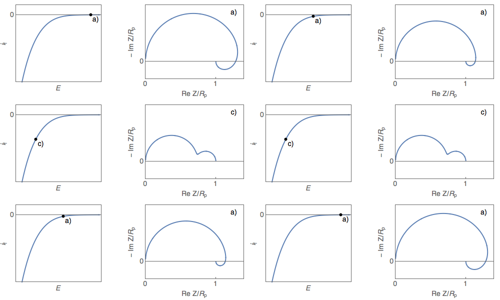
Two-step reactions (iron dissolution in acidic medium, Volmer-Heyrovský proton reduction) show a capacitive or inductive low-frequency arc depending on potential. The indistinguishability of the C1/R1/(R2 + L2) and C1/(R1 + C2/R2) circuits.
Key points
- In the Volmer-Heyrovský reaction the low-frequency arc of the impedance diagram changes from inductive to capacitive (or the reverse) as the electrode potential changes.
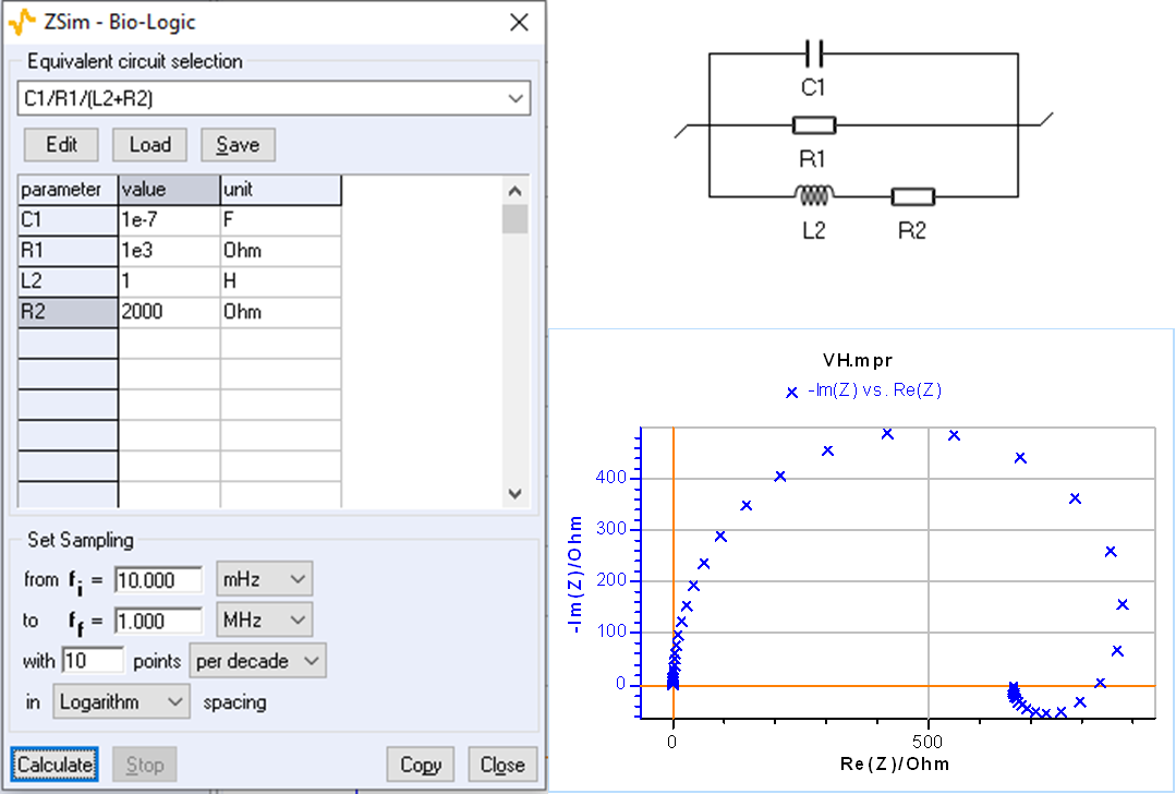
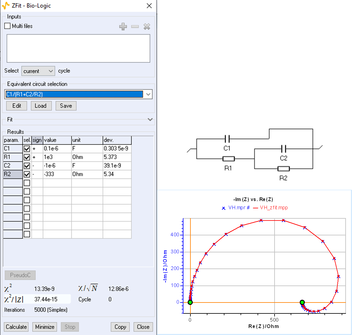
- The C1/R1/(R2 + L2) circuit produces a low-frequency inductive arc; the same data are fitted perfectly with C1/(R1 + C2/R2) by forcing R2 and C2 negative.
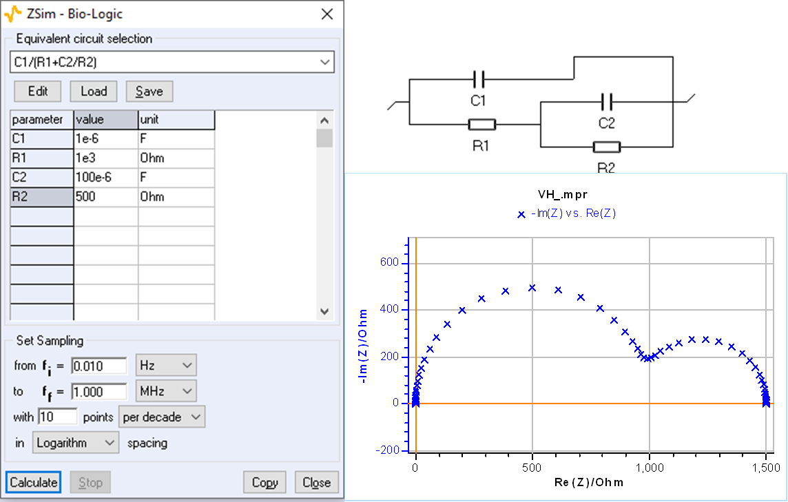
- Conversely, a capacitive arc simulated with C1/(R1 + C2/R2) is fitted with C1/R1/(R2 + L2) taking R2 and L2 negative.
- The two circuits are indistinguishable: they give the same impedance and the choice rests on physical interpretation. A negative adsorption resistance or capacitance arises from the kinetics of the adsorption step.
- In ZFit the sign of a parameter can be forced with the 'sign' box; because initial values are searched randomly, several attempts may be needed.
- The most common case is the unpolarised system, i.e. natural corrosion in acidic medium. The rest of the series covers why circle fitting is wrong, detecting inductive behaviour, high-frequency inductance, circuit choice, distinguishability and identifiability.
Figures
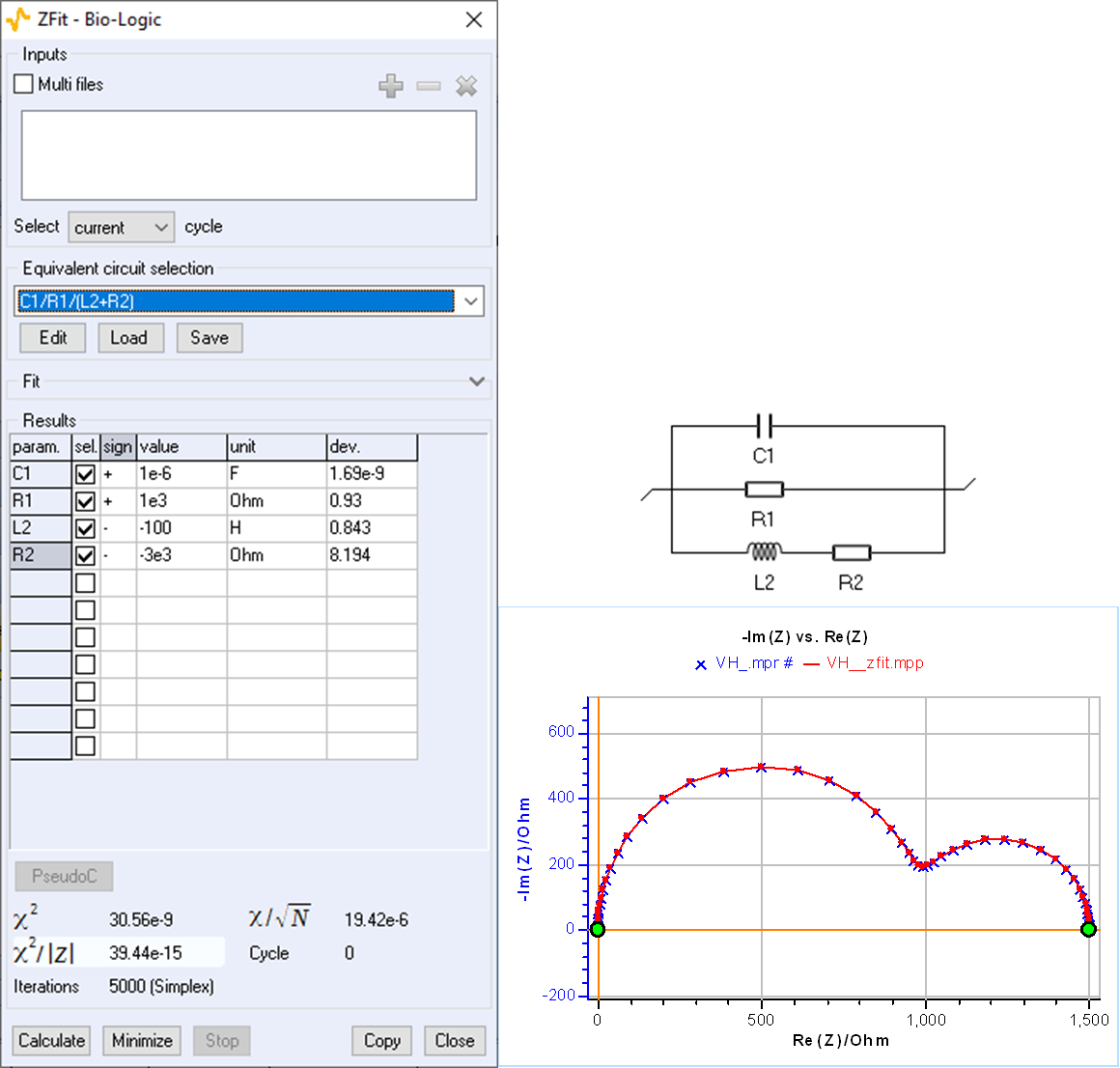
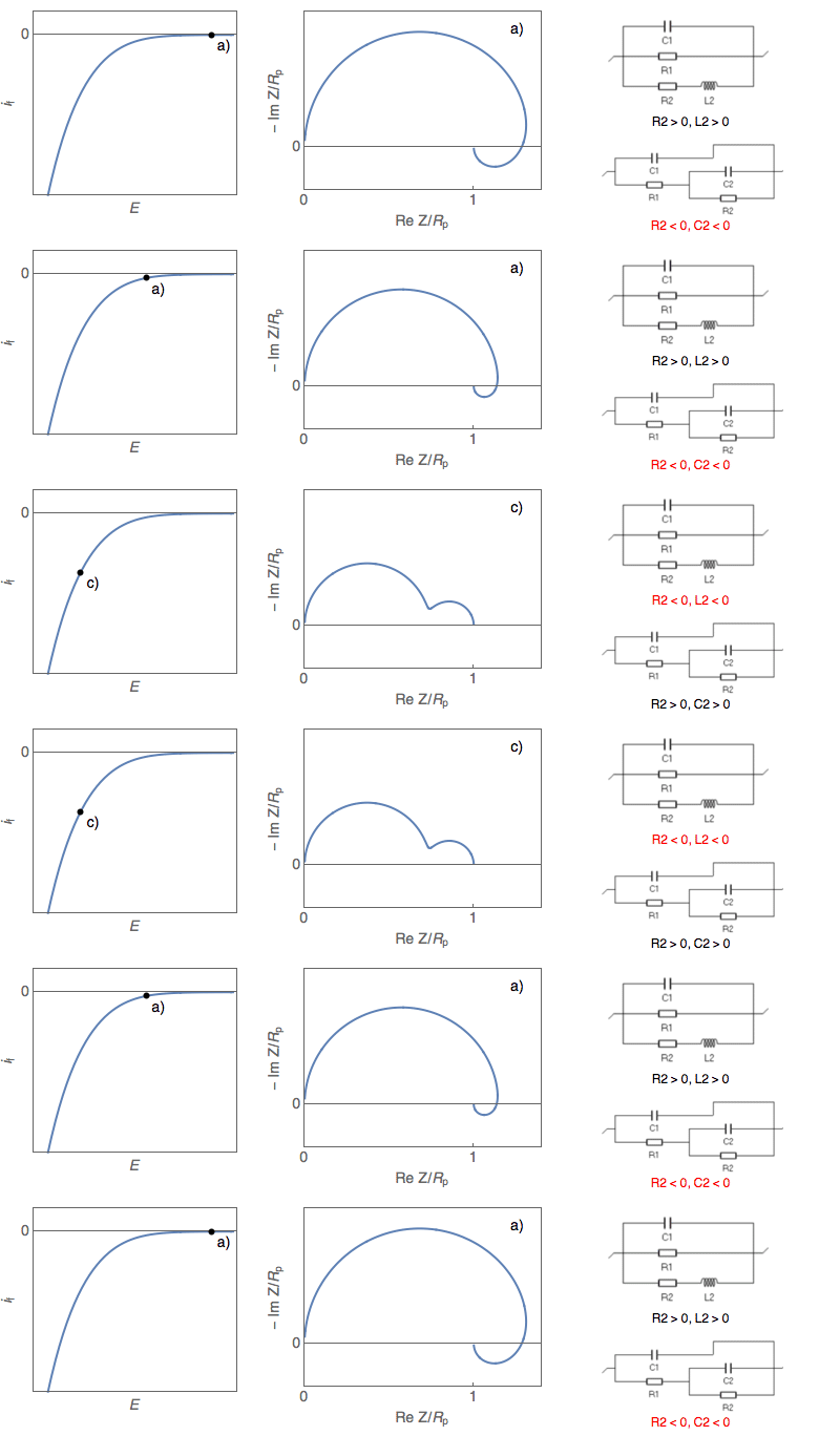
Images: Bio-Logic Science Instruments; taken from the source article.
Related application notes
Related curriculum module: Electrochemical Impedance Spectroscopy (EIS)
Source: Bio-Logic Learning Center, “ZSim and ZFit as learning tools. Part I – Acidic corrosion” · Source updated: November 18, 2024
Copyright of the images and the original text belongs to Bio-Logic SAS.
Copyright of the images and the original text belongs to Bio-Logic SAS.